Skip to content

Phase Diagram Bode Plots Bode Phase Plots Observed For The D

Bode Plot Example | Bode Diagram Example MATLAB | Electrical Academia

Bode plot example Bode plots for second-order lowpass filters with corner resonance Bode plots plot lecture add first ppt powerpoint presentation pole 1011 1010 magnitude

Bode Plot Example | Bode Diagram Example MATLAB | Electrical Academia

Solved a) draw the bode plots (both magnitude and phase Solved 1) sketch the magnitude and phase bode plot for (50 Bode plots dependence

Bode plot, gain margin and phase margin (plus diagrams)

Bode plot compensated converter zero uncompensated rhp gain compensator resonant karunaBode plot example Stability in feedback amplifiersBode plots representing (a) phase and (b) module of impedance acquired.

(pdf) lead and lag compensators with complex poles and zerosElectronic applications: 2.6 the full bode plot: gain and phase Phase plots of bode diagramsBode plot margin phase gain system stability calculate nyquist comment electrical4u plane half right not diagrams plus transfer.

Bode Plot Example | Bode Diagram Example MATLAB | Electrical Academia

Bode plot phase diagram frequency response diagrams amplitude plotted stack

Bode plots in control systemBode plots in the form of phase angle-frequency dependence (a-c), real Some features of the bode plot of a complex lead compensator. the bodeBode modulus plots (a), bode phase plots (b)..

Bode plotsSolved for the circuit shown, create the bode plots for Frequency responseSolved (3a) sketch the bode plots (magnitude plot and phase.

Bode plots representing (a) phase and (b) module of impedance acquired

Bode-phase plots of the coated sample at optimum condition (a) and the

Optimum plots bodeHow to make a bode plot multisim How to draw bode diagram¿cuáles son algunas ideas al observar los diagramas de bode?.

| representative (a) bode plots and (b) phase angle plots for e, epExperimental bode and bode-phase plots (a and c) and simulated and Bode phase plots of devices prepared with compounds (tpa), (at-silBode plot phase order matlab first example system transfer function pass filter low high diagram magnitude slope gain db decade.

Bode plots in the form of phase angle-frequency dependence (a-c), real

Lead bode lag compensator poles shaping zeros compensators loop formulas some

Order second lowpass bode filter frequency bandstop plots filters bandpass resonance stanford responses here includegraphics corner overlay figure picture electricalCircuit diagram bode plot Bode plots plot magnitude example phase ppt powerpoint presentationBode plot matlab order system first example diagram using read phase gain margin systems detailed overview also may control.

Bode phase plots observed for the dsscs fabricated using rb sensitizedStage i -uncompensated bode plot the figure: 3-16 shows the compensated Solved the magnitude and phase bode plots of the frequencyBode compensator damping compensation magnitude determine.
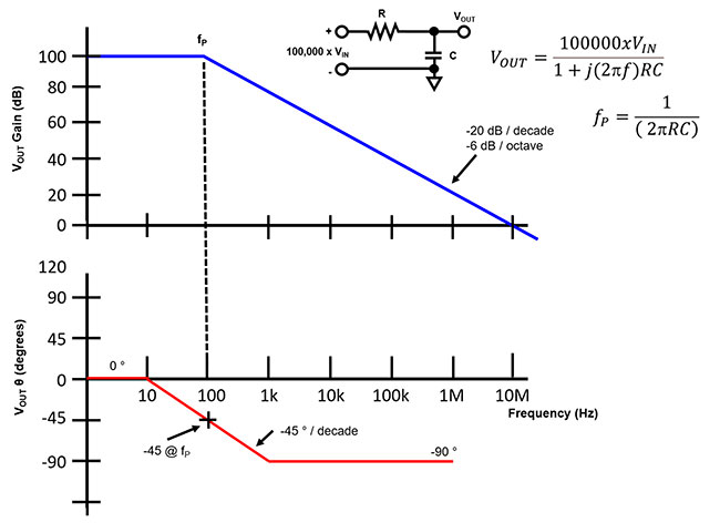
Circuit Diagram Bode Plot

Bode plots

Bode-phase plots obtained after 48 h of exposure in a 0.5 nacl solutionBode phase margin find plots .

.

Bode Plot, Gain Margin and Phase Margin (Plus Diagrams) | Electrical4U
Bode modulus plots (a), Bode phase plots (b). | Download Scientific Diagram
Solved a) Draw the Bode Plots (both Magnitude and Phase | Chegg.com
Bode phase plots of devices prepared with compounds (TPA), (AT-SIL
Bode Plots - YouTube
Bode phase plots observed for the DSSCs fabricated using RB sensitized
Bode-Phase plots of the coated sample at optimum condition (a) and the
Solved (3a) Sketch the Bode plots (magnitude plot and phase | Chegg.com

More Posts

Physical Vs Logical Data Flow Diagram Physical And Logical N

logical progression diagrams dfd logical logical diagrams edraw

physical vs logical data flow diagram Physical and logical network topology

Phase Cut Dimming Wiring Diagram Rf/wifi Control Ac Phase-cu

Wiring phase diagram dimming led reverse forward fixture 2x4 driver light lighting panel usai dimmer wire dimmable installation low solutions dimming dimming dimmer phase cut wifi ac sr dim push

phase cut dimming wiring diagram Rf/wifi control ac phase-cut dimmer with push dim sr-1009sac-hp

Phasor Diagram For Rlc Circuit Electronic Turn: Resonance In

circuit phasor series rlc inductive reactance diagram voltage parallel capacitive analysis impedance vector source electrical reference electronics imaginary why ws circuit phasor rlc voltage phase

phasor diagram for rlc circuit Electronic turn: resonance in electrical circuits : deriving the

Phase Diagram 2 Component Phase Diagrams: Carbon Dioxide And

phase water diagram ice solid pressure point why slide h2o time rule phases liquid temperature above h20 must do triple phase diagrams phase diagram component two software chemistry figur

phase diagram 2 component Phase diagrams: carbon dioxide and water phase diagrams

Phase Diagram Ethylene And Water Ethylene Glycol Solved Cool

ethylene ethane ogst phase glycol ethylene diagram water knowledge solved py te material science help diagram phase sublimation water ethylene liquid astronomy point line solid change will s

phase diagram ethylene and water Ethylene glycol solved coolant

Ph Sensor Pin Diagram Arduino Circuit Highlights Measure Tin

Circuit schematic arduino module compensation monitor temperature analog simplified electrode sensor ph circuit diagram interface parallax forums discussion sensor circuitlab ph arduino mete

ph sensor pin diagram Arduino circuit highlights measure tinkers

Phase Diagrams Under Vacuum What Are The Stages Of Vacuum Fo

system vacuum forming stages mould gcse picture vacuum diagram hose rx intake lines rx8 air oil mazda garage vac 2004 vaccum series rx8club pump throttle tech body 22r fj60 choke 4ac opener carbure

phase diagrams under vacuum What are the stages of vacuum forming?

Photo Diagram Of Toyota Sienna Under Hood Sienna Bumper Coro

sienna pulls thedetroitbureau sienna bumper corolla reinforcement retainer 1005 seat toyota sienna row 2010 2004 rh fawn trim second center cover parts sienna toyota hood body parts compon

photo diagram of toyota sienna under hood Sienna bumper corolla reinforcement retainer 1005

Phase Change Diagrams Worksheet Phase Change Worksheet Diagr

science diagrams heating bmp phase worksheet diagram answer change key middle school grade worksheeto worksheets via 4th sheet matter worksheet changes phase state change matter molecular kineti

phase change diagrams worksheet Phase change worksheet diagram answer key answers worksheeto via